Split Segments Toolkit
As explained in the Toolkits section, there is a dedicated toolkit for splitting segments in your volume annotation. With this toolkit activated, you can draw a curved 3D surface to split a segment into two along this interface.
Workflow
The recommended steps for splitting a segment are as follows:
- Use the bounding box tool to create a box around the merge error you want to correct. This step is optional, but relabeling large parts of a segment can be compute-intensive and limited by your machine's performance. For large-scale corrections, consider the proofreading tool. For ground-truth curation, local corrections are often sufficient.
- Go to the first z slice of the bounding box.
- Create a new skeleton tree and place nodes on the boundary that should split the segment into two. Consider activating the "Pen" mode within the skeleton tool so that you can rapidly draw nodes by dragging the mouse while it's pressed down.
- Go to the last z slice of the bounding box and repeat the previous step.
- Now you can inspect all the slices in between. A smooth spline curve will be shown in each slice that is derived from interpolating between adjacent slices. If you want to correct the interpolation, you can create new nodes on a slice. A new spline curve will be computed from these points and the interpolation will be updated.
- If you are satisfied with the (interpolated) boundary, you can switch to the fill tool and relabel one side, effectively splitting a segment into two. Ensure to enable the 3D mode as well as the "Restrict to Bounding Box" mode.
Troubleshooting
- It can easily happen that the flood-fill operation relabels the entire segment instead of only the part you intended to relabel. This is usually caused by the 3D surface not completely cutting through the segment. Instead, the surface might only go very close to the edge. In that case, the flood-fill operation can traverse over that edge and thus relabel everything (see image below). If this happens, you should undo the fill operation and double-check the surface. To avoid this problem, it is recommended to draw the splitting surface a bit bigger than the actual segment boundaries.
- If multiple spline curves appear per slice, this is often due to a configuration issue. Please adapt the clipping distance in the left sidebar (
Layers→Skeleton).
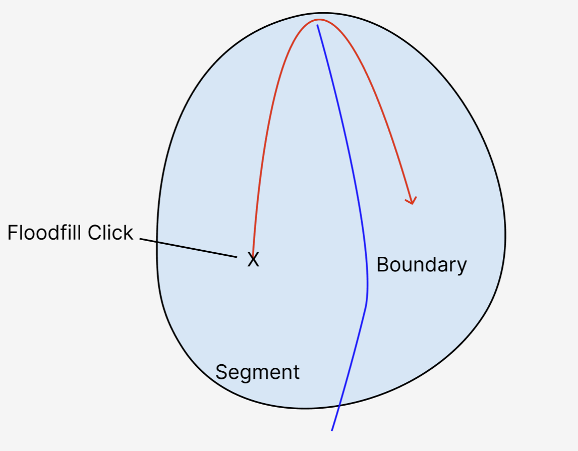
A visualization of a floodfill operation "bleeding" across the boundary because the boundary is not precise enough
Impact of "Split Segments" Toolkit
Note that the workflow above is only possible because the "Split Segments" toolkit is enabled. By activating that toolkit, WEBKNOSSOS behaves differently in the following way:
- The active tree will be rendered without any edges. Instead, for each slice in which multiple nodes exist, a spline curve is calculated that goes through these nodes.
- Using the spline curves from before, a 3D surface is generated that interpolates through these curves. The surface can be seen in the 3D viewport.
- The flood-fill tool will respect the splitting surface by not crossing it.
- Get Help
- Community Forums
- Email Support